The half adder and full adder
Binary arithmetic
The half adder and full adder are components of digital circuits that enable us to carry out binary addition. Using adders and half adders we can add two binary numbers together. Adders are a type of integrated circuit comprising certain logic gates where the arrangement allows for the representation of the addition of bits.
Example addition
Consider the following binary addition:
  c_1
0   0   1   0
0   0   1   1
_____________
0   1   0   1
How does the calculation proceed? Moving from the right-most column:
- \(1 + 0 = 1\) hence the sum of the first column (the binary 1 coumn) is \(1\) with no carry
- Moving to the second column (the binary 2 column), \(1 + 1 = 2\) however we do not have the digit “2” in binary, therefore we must bump the place value by one place and carry this sum as a \(1\) leaving a zero to mark the place value
- Thus the third column (the binary 4 column) has the calculation: \(1 + 0 + 0 = 1\) with no carry.
Bits
From the previous example we can identified the following repeated actions:
- For calculations of the form \(1 + 0\) or \(0 + 0\) there will be no carried digit
- For calculations of the form \(1 + 1\) there will be a carried digit
In the context of adders the digits are bits. We distinguish three core bits by their role in the calculation: the carry, the least significant bit and the most significant bit. The least significant bit is the right-most digit in the calculation. The most significant bit is the leftmost.
The two types of adders are distinguished by which bits of the calculation they operate on. The half adder focuses on the least significant bit whereas the full adder focuses on the most significant bit.
Half adder
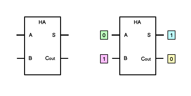
The half adder receives two bits (A and B) which are to be added together. It outputs this value as the sum bit. If there is a bit to be carried to the next column in the binary calculation this will be output as the carry-out bit.
| A | B | S | C_out |
|---|---|---|---|
| The first number to be added | The second number to be added | The sum bit | The carry-out bit |
The diagram below shows the circuit representation of a half-adder and an example calculation. This calculation matches the ones column of the earlier binary addition example: \(0011 + 0010\).

Implementation with logic gates
If we think about it, the possible inputs and outputs of a half adder are highly circumscribed:
- If the sum exceeds \(1\), the sum bit will be \(0\) and the carry-out bit will be \(1\)
- In all other cases the carry-out bit will be \(0\). These other cases are when the sum bit is either \(0\) or \(1\), e.g: \(1 + 0\) or \(0 + 0\).
We can represent this with a simple truth-table:
| A | B | S | C_out |
|---|---|---|---|
| 0 | 0 | 0 | 0 |
| 0 | 1 | 1 | 0 |
| 1 | 0 | 1 | 0 |
| 1 | 1 | 0 | 1 |
We can see that the sum bit column replicates the truth-conditions of XOR:
| P | Q | P V Q |
|---|---|---|
| T | T | F |
| T | F | T |
| F | T | T |
| F | F | F |
And the carry-out bit replicates the truth conditions of AND:
| P | Q | P & Q |
|---|---|---|
| T | T | F |
| T | F | F |
| F | T | F |
| F | F | T |
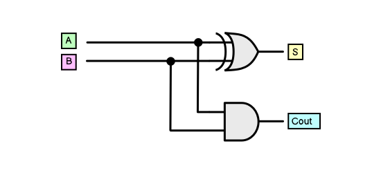
It is therefore possible to implement a half-adder with just these two logic gates:

The digital circuit above has the same inputs and outputs as the half adder diagram above.
Full adder
As the half adder only calculates the least significant bit, it is not sufficient by itself to complete a binary addition; it cannot account for movements in binary place value. To carry out full calculations it must be supplemented with the full adder.
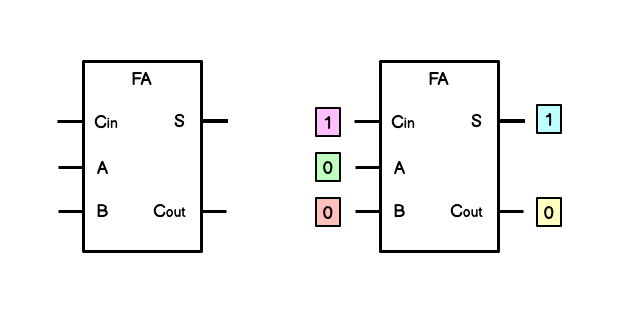
The full adder takes in three inputs and has two outputs. It is identical to the half-adder apart from the fact that one of its inputs is carry-in. This is equivalent to the value that is designated as carry-out in a half adder. It is an incoming value that is the product of a previous operation that resulted in a carry-out. This is added together with the full adders own two inputs (A and B) and like the half adder, generates a sum bit and a carry-out bit.
| A | B | C_in | S | C_out |
|---|---|---|---|---|
| The first number to be added | The second number to be added | The incoming carried bit | The sum bit (A+B+C_in) | The carry-out bit (A+B+C_in) |

The diagram above is equivalent to the calculation taking place in the fours column. It has received a carry from the twos column (\(1 + 1\) results in \(1\) as a carry) and then adds this together with its own inputs (\(0\) and \(0\)).
  c_1
0   0   1   0
0   0   1   1
_____________
0   1   0   1
Implementation with logic gates
When it comes to implementing the full adder with logic gates we can allow ourselves greater abstraction as we already have the half adder to work with. We don’t need to create a half adder from scratch, we can reuse it.
We are adding three bits: \(1\), \(0\) and \(0\). This can be achieved with two half adders:
- One half adder (HA1) for the sum of \(0 + 0\)
- One half adder (HA2) for the sum of \((0 + 0) + 1\) (the previous sum plus the third bit)
The sum of HA1 (\(0 + 0\)) is passed in to the B input on HA2 and the \(1\) is passed in as the A input of HA2. This gives us \(1\) as the sum bit of HA2.
At this point we have completed the addition and have successfully added the three bits: \(1\), \(0\), and \(0\) to get \(1\) as ths sum. However we also have to account for the fact that the addition may result in its own carry-out bit. What if the inputs were \(1, 1, 0\) for example?